Case study / 2026
TMR actuator driver PCB: 3-ECU voting and 24 output channels
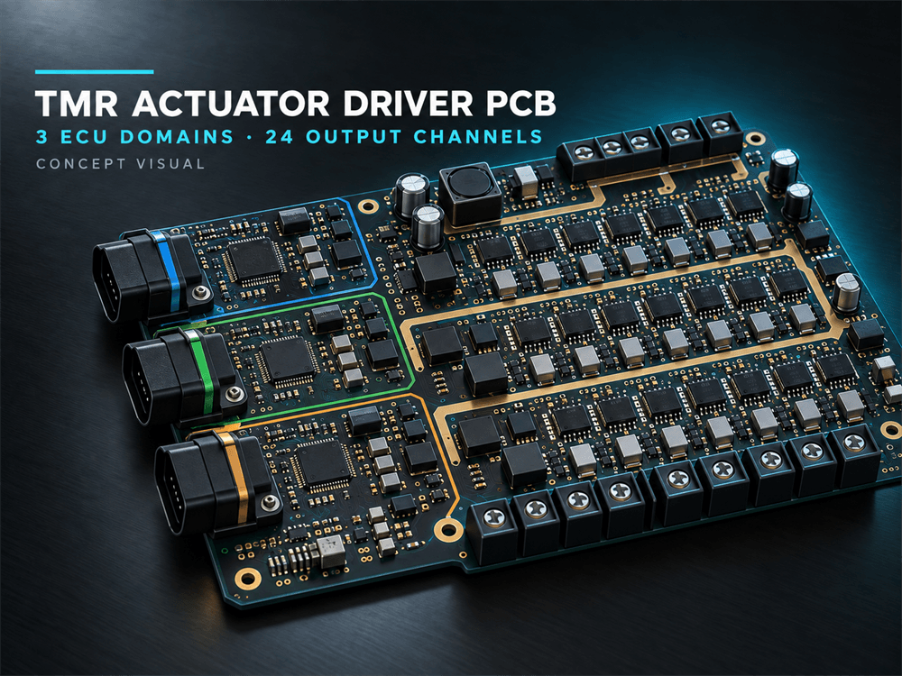
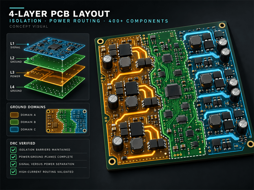
Four-layer PCB layout for a Triple Modular Redundant actuator driver board. The client supplied the schematic and architecture; the layout implements three isolated ECU domains and hardware 2-of-3 voting for 16 solenoid and 8 ignitor channels.
Engineering contribution
Role & scope
- Role
- PCB Layout Engineer — 4-Layer Safety-Critical Hardware
- Year
- 2026
Component placement, signal and power routing, isolation-barrier implementation, ground and power planes, DRC/ERC verification, and Gerber release. No claim is made for architecture design, certification, fabrication or operational validation.
Technical highlights
- 400+ component placement
- Three galvanically isolated ECU domains
- 16 solenoid + 8 ignitor channels
- Four-layer power and signal routing
Tools & skills
Altium DesignerGerberDRC/ERC4-layer PCBConstraint managementIsolation layoutPower planesDFM/DFA
Scope in context
Engineering concepts.
These visuals explain the project’s hardware scope. They are concept presentations, not photographs of fabricated client hardware.

Work with Dhara
Related services.
Your next board
Bring the requirements.
Let’s define the hardware.
Share your product goal, current files and constraints to discuss a defined PCB or embedded hardware engagement.
Discuss your project ↗